Ensemble Toolkit
The design and implementation of EnTK are iterative and driven by use cases. Use cases span several scientific domains, including Biomolecular Sciences, Material Sciences, and Earth Sciences. Users and developers collaborate to elicit requirements and rapid prototyping
Design
We describe how applications are modeled using EnTK components, the architecture and execution model of EnTK. We also specify the types of failures recognized by EnTK and how some of the failures are handled.
Application Model
We model an application by combining the Pipeline, Stage and Task (PST) components.
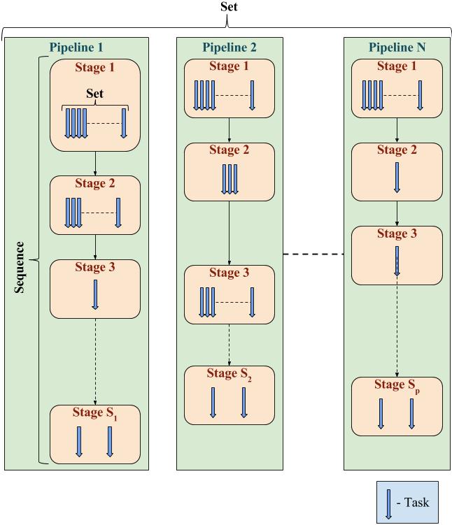
Figure 1: PST Model
We consider two pythonic collections of objects, Sets and Lists, to describe the task graph. A set-based object represents entities that have no relative order and hence can execute independently. A list-based object represents entities that have a linear temporal order, i.e. entity ‘i’ can only be operated after entity ‘i-1’.
In our PST model, we have the following objects:
Task: an abstraction of a computational task that contains information regarding an executable, its software environment and its data dependences.
Stage: a set of tasks without mutual dependences and that can be executed concurrently.
Pipeline: a list of stages where any stage ‘i’ can be executed only after stage ‘i–1’ has been executed.
When assigned to the Application Manager, the entire application can be expressed as a set of Pipelines. A graphical representation of an application is provided in Figure 1. Note how different Pipelines can have different numbers of Stages, and different Stages can have different numbers of Tasks.
By expressing your application as a set or list of such Pipelines, one can create any application that can be expressed as a DAG.
Architecture
EnTK sits between the user and an HPC platform, abstracting resource management and execution management from the user.
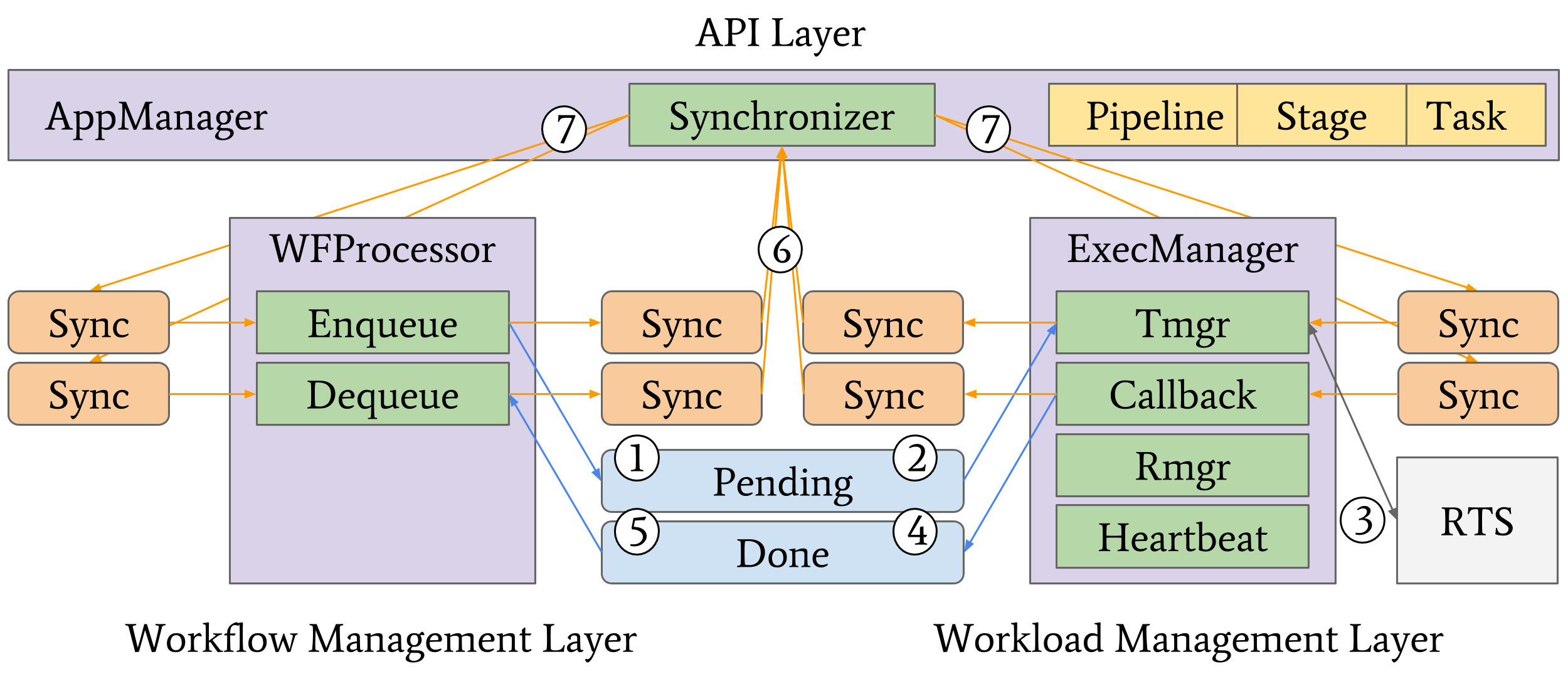
Figure 2: Ensemble Toolkit Architecture and Execution Model
Figure 2 shows the components (purple) and subcomponents (green) of EnTK, organized in three layers: API, Workflow Management, and Workload Management. The API layer enables users to codify PST descriptions. The Workflow Management layer retrieves information from the user about available HPC platforms, initializes EnTK, and holds the global state of the application during execution. The Workload Management layer acquires resources via the RTS. The Workflow Management layer has two components: AppManager and WFProcessor. AppManager uses the Synchronizer subcomponent to update the state of the application at runtime. WFProcessor uses the Enqueue and Dequeue subcomponents to queue and dequeue tasks from the Task Management layer. The Workload Management layer uses ExecManager and its Rmgr, Emgr, RTS Callback, and Heartbeat subcomponents to acquire resources from HPC platforms and execute the application.
This architecture is the isolation of the RTS into a stand-alone subsystem. This enables composability of EnTK with diverse RTS and, depending on capabilities, multiple types of HPC platforms.
Execution Model
Once EnTK is fully initialized, WFProcessor initiates the execution by creating a local copy of the application description from AppManager and tagging tasks for execution. Enqueue pushes these tasks to the Pending queue (Fig. 2, 1). Emgr pulls tasks from the Pending queue (Fig. 2, 2) and executes them using a RTS (Fig. 2, 3). RTS Callback pushes tasks that have completed execution to the Done queue (Fig. 2, 4). Dequeue pulls completed tasks (Fig. 2, 5) and tags them as done, failed or canceled, depending on the return code of the RTS. Each component and subcomponent synchronizes state transitions of pipelines, stages and tasks with AppManager by pushing messages through dedicated queues (Fig. 2, 6). AppManager pulls these messages and updates the application states. AppManager then acknowledges the updates via dedicated queues (Fig. 2, 7). This messaging mechanism ensures that AppManager is always up-to-date with any state change, making it the only stateful component of EnTK.
Failure Model
We consider four main sources of failure: EnTK components, RTS, HPC platform, and task executables. All state updates in EnTK are transactional, hence any EnTK component that fails can be restarted at runtime without losing information about ongoing execution. Both the RTS and the HPC platform are considered black boxes. Partial failures of their subcomponents at runtime are assumed to be handled locally. Platform-level failures are reported to EnTK indirectly, either as failed pilots or failed tasks. Both pilots and tasks can be restarted. Failures are logged and reported to the user at runtime for live or postmortem analysis
Implementation
EnTK is implemented in Python and uses RADICAL-Pilot (RP) as its runtime system. RP is designed to execute ensemble applications via pilots. Pilots provide a multi-stage execution mechanism: Resources are acquired via a placeholder job and subsequently used to execute the application’s tasks. When a pilot is submitted to an HPC platform as a job, it waits in the platform’s queue until the requested resources become available. At that point, the platform’s scheduler bootstraps the job on the requested compute nodes.
You can view the class diagram and sequence diagram and more in the developer documentation.
Performance
Below we present the weak and strong scaling behavior of EnTK on the ORNL Titan machine.
Detailed description of the experiments can be found in this technical paper.

Figure 3: Weak scalability on Titan: 512, 1,024, 2,048, and 4,096 1-core tasks executed on the same amount of cores
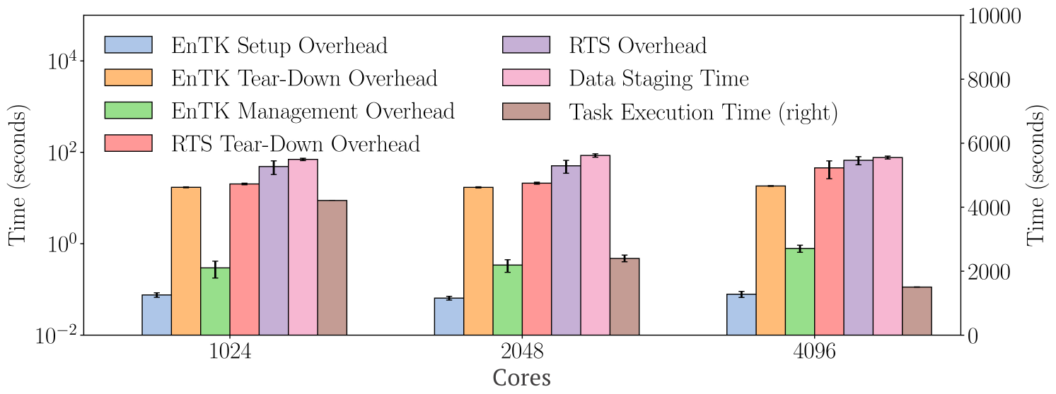
Figure 4: Strong scalability on Titan: 8,192 1-core tasks are executed on 1,024, 2,048 and 4,096 cores